|
||||
| Also available as an Acrobat File | 

|
|
Methodology |
The Application of Digital Photogrammetric Techniques and Aerial Photography to
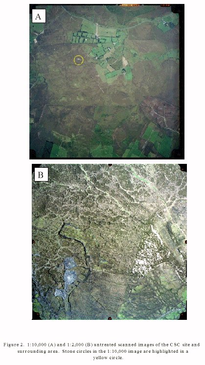
the Preservation of Archaeological Detail. 3 Methodology3.1 Data sourceThe scanned aerial photographs were transferred onto CD in the Helava Vitec Tile format (1:10000 scale) and standard Tiff format (1:2000 scale). These images were imported directly into the (DPW). The DPW runs a software package called Socet Set that is used to carry out all of the image manipulations and digital terrain model generation detailed in this study. 3.2 Ground SurveyAccurate control points are needed to tie the pair of stereo images to each
other and to facilitate the construction of an accurately constrained product
for spatial measurements. For the 1:10000 scale imagery Ground Control Points
were identified from the aerial photographs and were surveyed in the field
using a Leica Wild GPS 200 (differential GPS system). For the 1:2000 images,
it was possible to place marker sheets in specific positions around the site
that were included in the acquired images. The absolute positioning of these
sheets was measured prior to image acquisition. GPS data was processed and
geographic latitudes, longitudes and elevations generated using Leica SKI v
2.01 software. The values for each GCP were then input into the DPW to allow
accurate calibration and rectification to be carried out on the images. In
preparation for the more detailed examination of the stone circles, relative
heights of selected stones were also recorded for comparison with the digital
terrain models to be generated.
3.3 Image Preparation (orientation)When images are obtained by photographic techniques, aberrations in the lens can distort the image. Clearly, these distortions give a significant error to any measurements made upon the images and prevent the accurate registration of the images that allows three-dimensional viewing. These are removed by the DPW by inserting the details of the lens distortions provided in the lens calibration report that accompanies the image files. Using the lens calibration files this first stage in image preparation was carried out. This procedure is referred to as Interior Orientation and is a basic procedure in image processing. The next step in image preparation (Exterior Orientation) includes two distinct processes (triangulation and rectification) that are used to prepare the images for stereoscopic examination and data extraction 3.4 Triangulation and RectificationThe images were registered to the ground using the Helava Automatic
Triangulation System (HATS) component of Socet Set. Initially, the DPW creates
a number of points on each image and finds the corresponding points in
overlapping areas of both images (these are called Tie Points). |
Graphics Multimedia Virtual Environments Visualisation Contents