|
||||
| Part One: A Guide to VRML 2.0 |     
|
This section will introduce the main features of the VRML 2.0 language and demonstrate with examples how they can be used to create interactive and animated virtual scenes. The example worlds used in this section can also be found online at:
http://www.mmu.ac.uk/art-des/arc/vrml2proj/ For a more detailed explanation of all the many powerful capabilities of VRML 2.0 language, the reader should refer to the online tutorials listed in at the end of this section or to the other internet resources and publications listed in Section 7. A list of all the VRML 2.0 nodes can also be found in Appendix A.
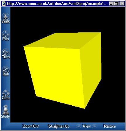
Figure 3-1 Example 1, viewed with WorldView Figure 3-1 shows a simple VRML world, consisting of a single yellow box shape. The VRML file that describes this scene is listed below. Because a VRML file is written in plain text, any ordinary text editor (such as WordPad or vi) can be used to create it. Simply save the file with a .wrl extension, then open the file again with a VRML browser in order to view the model in three-dimensions.
#VRML V2.0 utf8
# example1.wrl - a yellow box
Shape {
    geometry Box { }
    appearance Appearance {
        material Material {
            diffuseColor    1.0  1.0  0.0	 # red, green, blue
        }
    }
}
The VRML 2.0 Header and Comments
The first line of the VRML file contains the header #VRML V2.0 utf. This identifies it as a VRML 2.0 file, as opposed to a VRML 1.0 file, for example. All VRML files must start with this header. The utf keyword refers to the UTF-8 international character set used in the file.
The second line starts with the `#' symbol. This indicates that all the text with follows it, until the end of the line is a comment, and should be ignored by the VRML software. In the example, the comment describes the contents of the scene.
Nodes and the Scene Graph
The rest of a VRML file consists of a list of nodes, each of which contain part of the information that describes the whole scene, for example, it may define a shape or light source or particular properties of an object, such as its colour or coordinates. Each node consists of a name, that indicates the node's type, followed by a set a curly braces containing zero or more fields, that define the attributes of that node. A field statement consists of the field name followed by one or more values. Fields can be written in any order. Node type names start with a capital letter, field names begin with a lower case letter.
In the example, the nodes used are Shape, Box, Appearance and Material. The Shape node contains two fields, geometry and appearance, each of which require other nodes as their values. The geometry field contains the Box node and the appearance field takes the Appearance node as its value. The Appearance node then in turn contains another node, called Material. This hierachical structure of nodes contained within other nodes is called the scene graph.
The Box node, Fields and Field Values
The Box node has a single field called size, which sets the dimensions of the box shape that is to be drawn. The field name is followed by three values that define the lengths of the sides, parallel to the X, Y and Z axes respectively, with the centre of the box at the origin. For example, the following node defines a box shape 3 units wide, 2 units high and 5 units deep.
Box {
    size  3.0  2.0  5.0
}
However, the example world does not specify a size for the box, therefore the VRML browser will use the default values for these attributes when it displays the scene. A list of all the VRML nodes and their default field values can be found in Appendix A . The different data types the fields expect are also described.VRML Units and Coordinate System
The VRML specification recommends that metres are used as units of distance. Using a common unit of measurement makes it easier to share models. However, using metres may not always be convenient. Time is always defined in seconds and angles in radians.
VRML uses a right-handed coordinate system. By default, the viewer is on the Z-axis looking towards the origin with the X-axis to the right and Y-axis upwards.
Appearance and Material
Having defined the object's geometry through the Box node, it is now necessary to describe the object's colour and surface properties using the Appearance node. The Appearance node has three fields, material, texture and textureTransform. The last two fields are used when applying textures to an object, this is described in more detail later. The material field takes the Material node as its value. If the Appearance node is left undefined the object will be rendered as pure white. The Material node specifies the colour and reflective properties of an object with six fields.
* The diffuseColor field defines the base colour of the object, that is reflected in all directions when it is illuminated. The colour is specified using three floating point numbers ranging between 0.0 and 1.0 and representing the amounts of red, green and blue. The default value is 0.8 0.8 0.8, which is a grey colour.
- The specularColor field defines the colour of the shiny highlights on the object. By default this is 0.0 0.0 0.0 (black).
- The emissiveColor field specifies the colour given off by objects, independent of any light sources. The default value is 0.0 0.0 0.0 (black).
- The shininess value controls the sharpness of the specular highlight. Increasing this value will make the object appear more shiny. the default value is 0.2.
- The transparency field specifies how "clear" the object is. A value of 0.0 (default) indicates an opague object, 1.0 indicates full transparency.
- The ambientIntensity value is used to simulate ambient (indirect) lighting of the object. the default value is 0.2. In the first example, only the diffuseColor field is required to define a basic yellow colour for the box shape. The next example will show how the other fields can be used to create different effects.

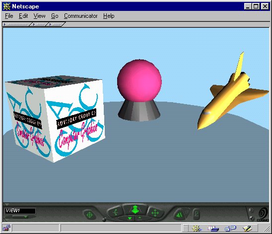
Figure 3-2 Example 2, displayed by Cosmo Player The second example VRML world (Figure 3-2) demonstrates more object types, environmental and material properties and includes animations and user interaction. The scene consists of a semi-transparent table top with three objects positioned upon it. The first object is a globe, consisting of a sphere on a base. The colour of the sphere will slowly change. The second object is a texture-mapped box. The box also rotates and forms a hyperlink to the AGOCG home page. The final object is an inlined model of the Space Shuttle, which the user can manipulate.
The VRML file which describes this scene is listed below. The line numbers to the left of the code are included for reference purposes, and are not part of the VRML document.
1   #VRML V2.0 utf8
2   Group {
3       children [
4           # Define initial viewpoint
5           Viewpoint {
6               position    0 4 8
7               orientation 1 0 0 -0.46
8               description "VIEW1"
9           }
10
11          # Make background a light blue colour
12          Background { skyColor [0.65, 0.86, 0.99]}
13
14          # A point light source to illuminate scene
15          PointLight { location 10 0 10 }
16
17          # Semi-transparent table top
18          Shape {
19              appearance Appearance {
20                  material Material { transparency  0.5 }
21              }
22              geometry Cylinder {
23                  radius 5
24                  height 0.1
25              }
26          }
27
28          # The globe: a sphere on a cone base
29          Transform {
30              translation  0.0  1.1 -2.0
31              children [
32                  Shape {                                 # The base
33                      appearance Appearance {
34                          material DEF BaseMaterial Material {
35                              diffuseColor    0.2  0.2  0.2
36                              specularColor   0.4  0.4  0.4
37                          }
38                      }
39                      geometry Cone { }
40                  }
41                  Transform {
42                      translation  0.0  0.5  0.0
43                      children [
44                          Shape {                         # The sphere
45                              appearance Appearance {
46                                  material DEF SphereColour Material { }
47                              }
48                              geometry Sphere { }
49                          }
50                      ]
51                  }
52              ]
53          }
54
55          # Hyperlinked 'AGOCG' box
56          Anchor {
57              url "http://www.agocg.ac.uk"
58              description "AGOCG Home Page"
59              children [
60                  DEF BoxTransform Transform {
61                      translation  -2.6  1.1  1.0
62                      children [
63                          Shape {
64                              appearance Appearance {
65                                  material USE BaseMaterial
66                                  texture ImageTexture {url "agocg_logo.gif"}
67                              }
68                              geometry Box { }
69                          }
70                      ]
71                  }
72              ]
73          }
74
75          # Inline shuttle model
76          DEF ShuttleTransform Transform {
77              translation  2.6  1.6  1.0
78              scale 0.2 0.2 0.2
79              children [
80                  Inline { url "shuttle.wrl" }
81                  DEF ShuttleSensor SphereSensor { }
82              ]
83          }
84
85          # Clock to drive animations
86          DEF Clock TimeSensor {
87              cycleInterval 10.0      # 10 second animation
88              loop          TRUE      # animation repeats forever
89          }
90
91          # Colour changes for sphere
92          DEF NewColour ColorInterpolator {
93              key       [0.0,         0.33,        0.66,        1.0]
94              keyValue  [1.0 0.2 0.2, 0.2 1.0 0.2, 0.2 0.2 1.0, 1.0 0.2 0.2 ]
95          }
96
97          # Rotation for 'AGOCG' box
98          DEF BoxRotation OrientationInterpolator {
99              key      [0.0,              0.5,              1.0]
100             keyValue [0.0 1.0 0.0 0.00, 0.0 1.0 0.0 3.14, 0.0 1.0 0.0 6.28]
101         }
102     ]
103 }
104
105 # Animate sphere
106 ROUTE Clock.fraction_changed TO NewColour.set_fraction
107 ROUTE NewColour.value_changed TO SphereColour.set_diffuseColor
108
109 # Animate 'AGOCG' box
110 ROUTE Clock.fraction_changed TO BoxRotation.set_fraction
111 ROUTE BoxRotation.value_changed TO BoxTransform.set_rotation
112
113 # Animate model shuttle
114 ROUTE ShuttleSensor.rotation_changed TO ShuttleTransform.set_rotation
Group Node (line 2)
The purpose of the Group node is to group together other nodes. The grouped nodes are listed in the children field. In the example, the Group node contains all the other nodes in the file (the closing bracket of the node is on line 103), so forming a single root node for the whole scene.
Viewpoint Node (line 5)
The Viewpoint node specifies the position and orientation of a favoured view within the VRML scene. When a VRML browser loads a VRML world containing a Viewpoint node, the scene will be initially displayed from that viewpoint. A VRML file can contain any number of Viewpoint nodes, although only one can be in use (bound) at a time. So, when a browser loads a world with multiple viewpoint definitions it will initially bind to the first viewpoint listed in the file. However, most VRML browsers also provide a menu in their user interface to allow the user to select between the different predefined viewpoints.
Background Node (line 12)
In the example, the Background node is used to specify a simple light blue background colour for the world. However, more complicated backgrounds can be defined with this node, using colour gradients and panorama images, such as mountain ranges or cityscapes.
Scene Illumination (line 15)
The example world contains a single point light source, located at (10 0 10). It is not essential to include a light source in a VRML world, since VRML browsers usually have a "headlight" mode to illuminate the scene immediately in front of the viewer. However, adding lights can often enhance the appearance of a scene.
There are three types of lighting nodes in VRML. DirectionalLight is used to simulate illumination from a far away light source, such as the sun. Since all the light rays are parallel (i.e. have the same direction vector), this is the easiest type of lighting for a browser to calculate. The PointLight node is used in the example, this models a point light source that sends out light with equal intensity in all directions. As well as the location field, there are fields for controlling how the intensity of the light diminishes with distance. Finally, there is a SpotLight node that
only illuminates objects within a specified cone-shaped space.Note that the light from VRML light sources is not stopped when it hits an object, but goes straight through, so there are no shadows. However, there are various techniques that can be used to "fake" shadows, such as texture mapping.
The Table Top (lines 18 to 26)
The table top is modelled using a flattened cylinder shape. The geometry is defined using the Cylinder node. VRML has four primitive geometry nodes: Box, Cone, Cylinder and Sphere. All four are used in this example world. Each node has fields to specify the dimensions of the shape and in addition, the Cone and Cylinder nodes have fields which control whether particular sides are shown. So, for example, by making the side and bottom fields of the Cylinder node FALSE, a disc shape can be produced.
To simulate a semi-transparent glass table top, the transparency value in the shape's Material node is made 0.5.
Transform Node
In order to move (translate), rotate or scale an object the Transform node is used. The effect of the node is to create a new coordinate system, which is used by all the children nodes of the transform. A Transform node can be a child of another transform, so producing a hierarchy or stack of coordinate transformations. This is demonstrated in the example world when defining the globe shape. The first Transform node (line 29), moves the globe's base to (0, 1.1, -2) in the world coordinate system. The second transform (line 41), which is a child of the first, moves the sphere part of the globe upwards by (0, 0.5, 0) relative to the position of the base part. Hence, the globe is positioned at (0, 1.5, -2) in the world coordinate system.
Naming Nodes with DEF
VRML allows a name to given to a node, using the DEF syntax:
DEF NodeName NodeType { ... } A node name must start with a letter and not contain any spaces. In line 34 the Material node for the globe's base is named BaseMaterial, and in line 46 the sphere's Material node is named SphereColour. Node names are required when reusing nodes and when defining animations, both of which are described later.
Anchor Node (line 56)
The Anchor node creates a hyperlink to a resource specified by the url field of the node. This could be another VRML world, a HTML page or any other type Web document. In order to activate the link the user must click on any of the objects defined in the children field of the Anchor node. In the example this is the texture mapped AGOCG box. The description field contains extra information about the link that can be displayed by the VRML browser.
Instancing (line 65)
The box has the same shiny dark grey material properties as the globe base, so instead of rewriting the whole Material node and its values, the USE syntax is used:
USE NodeName Where NodeName is the name of the node previously defined in the file using the DEF syntax, which in our example is BaseMaterial. This re-use of nodes, is called instancing. As well as saving space within a file, instancing enables any changes made to the properties of the original node to be carried forward to all of its instances.
Texture Mapping (line 66)
The box shape has an image of the AGOCG logo on each of its faces. This is achieved by using an ImageTexture node in the texture field of the shape's Appearance node. The ImageTexture node has a url field which specifies the location and name of the image file to be applied to the shape. In the example a relative URL is used because the agocg_logo.gif file is in the same directory as the .wrl file. Note that the texture overrides the diffuseColor property of the Material node.
Nearly all VRML browsers will accept JPEG and GIF (including transparent) formats for texture mapping. The VRML specification also says that the PNG format should be supported, although currently not all browsers do (see Section 2.0).
The position, scale and orientation of the texture can be controlled using the TextureTransform node in the Appearance node. By default, a texture image will be repeated when mapped on a surface, this can be turned off using repeatS and repeatT fields of the ImageTexture node.
The PixelTexture and MovieTexture nodes can also be used within the texture field of the Appearance node. The PixelTexture node records the texture image data within the VRML file itself, instead of an external image file. The pixel values are specified in the uncompressed SFImage format (see Appendix A). The MovieTexture node is used to specify a movie file (for example, in a MPEG format) for texture mapping.
Inline Node (line 80)
The final object in the scene is a model of the Space Shuttle. The Shuttle's geometry and appearance are actually defined in separate VRML file called "shuttle.wrl". The Inline node is used to tell the VRML browser to fetch the VRML file from the location specified in the url field and insert it into this world. Inlining is useful because it enables objects to be reused in different scenes and helps make large worlds more manageable.
The scale field (line 78) of the Shuttle's Transform node is used to reduce the size of the model by one-fifth, so that it can fit on the table top.
SphereSensor Node (line 81)
The Transform node also contains a SphereSensor node, which has been named ShuttleSensor. A sensor node detects viewer actions with the mouse pointer. When a viewer clicks on a shape in the same group as the sensor node, it generates events that can be used to start or control animations.
The SphereSensor node senses the user's click-and-drag action over the Shuttle shape, and computes a rotation value. This rotation value is then used to change the orientation of the Shuttle model using the ROUTE mechanism, which is described later. Other types of pointing-device sensor nodes are TouchSensor, CylinderSensor and PlaneSensor.
Events
Animation occurs in a VRML world, when the properties of a node, as defined by its field values are changed. To change one of these values it necessary to send the node an event created by another node. The event received by a node is called the eventIn and the event sent by a node is called the eventOut. Each node type accepts and generates different types of events, these are all listed in the Node Reference section in Appendix A. For example, the SphereSensor node produces an eventOut called rotation_changed which has a SFRotation value type.
A node field that has an implicit eventIn and eventOut is known as an exposedField. The name of the eventIn is the same as the exposedField, except that it has a set_ prefix. Similarly, the name of the eventOut has a _changed suffix.
TimeSensor Node (line 86)
The TimeSensor node generates time related events that are used to control the animations, essentially it is the clock for the VRML world. In the example, the cycleInterval and loop fields are used to define a 10 second animation that repeats continuously. It produces a floating point fraction_changed eventOut value that changes from 0.0 to 1.0 over the 10 second period.
The Interpolator Nodes (lines 91-101)
Interpolator nodes describe the changes that occur during an animation. They receive a single floating point eventIn value (set_fraction) and using the key and keyValue values defined within the node, compute a new (value_change) eventOut value, which can then be used to change the properties of other nodes.
The key field is a list of floating point values, usually representing points in fractional time. The keyValue field contains a list of corresponding eventOut values for each key value. When the eventIn value lies between key values, the eventOut value is determined using linear interpolation.
In the example, the ColorInterpolator produces a colour value that is used to vary the diffuse colour property of the sphere shape. The keyValue field specifies four different RGB colours at fractional times 0.0, 0.33, 0.66 and 1.0. So, at the start of the animation the sphere is red, gradually changing to a green colour after 3.3 seconds, then blue after 6.6 seconds, finally red again after 10 seconds, and then repeating.
The OrientationInterpolator (line 98) defines a steady rotation of the box shape about its vertical y-axis. One complete rotation (2[pi] radians) takes 10 seconds.
Other types of interpolator nodes are CoordinateInterpolator, NormalInterpolator, PositionInterpolator and ScalarInterpolator.
Routes
In order for a node to receive an event from another node, they must be connected using a ROUTE statement. Routes are usually listed at the bottom a VRML file. The general syntax is:
ROUTE Node1.eventOut TO Node2.eventIn Note that a node must be named with a DEF, for it to be able to send or receive an event through a ROUTE. Also, the eventIn and eventOut fields must have the same data type.
For example, the ROUTE statement in line 106, sends a SFFloat value from the fraction_changed eventOut field of the ClockSensor node (named Clock) to the set_fraction eventIn field of the ColorInterpolator (NewColour) node. In the next line, the SFColor value computed by the ColorInterpolator node, as a result of receiving the set_fraction value, is sent to the set_diffuseColor field of the sphere shape's Material node (named SphereColour, line 46), causing the sphere's diffuse colour properties to change.
Lines 110 and 111 contain the two ROUTE statements necessary to link the Clock event to the OrientationInterpolator, and then pass the SFRotation value it produces to the set_rotation field of the Transform node that controls the orientation of the box shape (line 60). Note how two separate animations statements share the same eventOut of the TimeSensor node.
The final ROUTE statement in the VRML example (line 114), animates the model of the Space Shuttle by sending the SFRotation value produced by the SphereSensor node (line 80) to the Shuttle's Transform node (line 76).
Summary
The two example worlds have been used to introduce many of the main features of the VRML language, including:
However, there are many more powerful features included in the VRML 2.0 specification. These are summarized in the following sections.
- Creating shapes using Cube, Cone, Cylinder and Sphere geometry nodes.
- Defining backgrounds, light sources and viewpoints.
- Applying different material properties to shapes.
- Grouping nodes and applying transformations (translation, scale, rotation)
- Texture mapping
- Hyperlinking
- Using inlines
- Naming nodes with DEF and reusing them with USE
- Creating animations and interactivity using sensor and interpolator nodes and the ROUTE statement.
The last example has shown how the primitive geometry nodes can be used to create a variety of simple shapes. But, for more complex shapes, such as the inlined Space Shuttle model, it is necessary to use the IndexedFaceSet node, which explicitly defines the coordinates of each face.
The following code demonstrates how the IndexedFaceSet node can be used to define a single square shape on the Z=0 plane. First, the 3D coordinates of the square are listed using the Coordinate node, then the coordIndex field describes the order in which the coordinate points should be joined together to form a single face. The order is important because it defines which side of the face is the front. By default, only the front face is rendered. Both sides are rendered if the solid field is made FALSE.
#VRML V2.0 utf8
Shape {
    geometry IndexedFaceSet {
        coord Coordinate {
            point [ 0 0 0, 1 0 0, 1 1 0, 0 1 0 ]
        }
        coordIndex [ 0, 1, 2, 3, -1]  # -1 indicates end of index list
    }
}
There is also a PointSet node that defines a set of points and a IndexedLineSet node for defining a 3D polyline. Text shapes are added to a VRML world using the Text geometry node. The FontStyle node is used to specify the characteristics of this text.
Complex shapes can also be created using the Extrusion node. This node describes a shape using a cross section that is extruded along a 3D spine. Finally, there is the ElevationGrid geometry node that provides an efficient method for specifying terrain surfaces, using a regular grid of height points.
The LOD (level of detail) node enables scenes to be displayed more efficiently by the VRML browser, by providing high and low detailed versions of an object. When a viewer is close to an object the high detailed version is displayed, but when the viewer is far away the low detailed version is used.
The LOD node groups together the nodes that form the alternative representations of the object and specifies the viewing distances at which the browser should switch between representations.
The Switch node can also be used to group together different versions of an object. The value of the whichChoice field determines which version is displayed.
Sound
Sound can be added to a VRML world with the Sound node. The node specifies a sound's location, direction, loudness and range. The source of the sound is defined using either an AudioClip or MovieTexture node. The AudioClip node contains the URL of the sound file (WAV or MIDI type 1 formats) and describes how it is played.
Billboard
The Billboard node is a group node, that automatically rotates its child shapes about a specified axis, so that the same side always faces the viewer.
Geometric Property Nodes
The Color node contains a list of colours that can be used in conjuction with the Coordinate node, to specify the colour properties of individual vertices, faces, lines or points. The TextureCoordinate node is used in the IndexedFaceSet and ElevationGrid nodes to control texture mapping on these surfaces. Vertex and face normals are used by the VRML browser to determine surface shading. By default, the browser will generate the normals automatically. However, it is possible to specify them explicitly within the VRML file, using the Normal node.
Viewer Detection
Most VRML browsers implement collision detection in 'walk' or 'fly' viewing modes, to prevent the user moving through objects. The Collision grouping node can be used turn off collision detection for its children or generate collision events that can be used for animations or sound effects. A collision bounding box can also be specified for a group of objects. This helps improve browser efficiency, by reducing the number of collision detection calculations required. The ProximitySensor node senses when the viewer enters or moves within a defined box-shaped region. The VisibilitySensor detects when a defined box-shaped region is visible from the viewer's current position and orientation.
World and Avator Properties
Atmospheric effects can be added to the VRML world, using the Fog node. The NavigationInfo node specifies the navigation mode that should be used by the VRML Browser when it loads the world. The standard navigation type values are 'EXAMINE', 'FLY', 'WALK', 'NONE' and 'ANY'. The first three navigation types are discussed in section 2.1, a 'NONE' value indicates that navigation should be disabled. The NavigationInfo node is also used to set the size and speed of the avator (the symbolic representation of the viewer in the virtual world), whether the headlight should be on or off and the maximum distance the avator can see. Finally, the WorldInfo node can be used to provide the VRML world with a title, and include additional information such as copyright details.
The example world described above, used VRML sensor and interpolator nodes to animate the objects. However, these nodes alone can only describe relatively simple actions. More complex animations and behaviours, such as a simulation of a bouncing ball or the switching of a light source on and off, require special purpose sensors and interpolators created with the general purpose Script node.
Like all VRML nodes, the Script node has a list of fields, eventIns and eventOuts, forming the node's interface declaration. The actions of the node are defined by a program script, that is specified in the url field. Typically, a program script will describe how an eventOut value is determined when an eventIn is received. Program scripts may also communicate with external sources, such as a server or a Java applet in a HTML page.
Program scripts can be written in any language that is supported by the VRML browser (see section 2.0). This is usually Sun Microsystem's Java language or Netscape's JavaScript (ECMAScript standard). Some browsers support VRMLScript, a subset of JavaScript language.
The Script node's url field specifies the location of the program script code, or can contain the code itself if JavaScript is used. For example, the following Script node uses JavaScript to describe the same rotation action defined by the OrientationInterpolator node in line 98 of the second example world.
DEF JSBoxRotation Script {
    eventIn SFFloat set_fraction
    eventOut SFRotation value_changed
    url "javascript:
        function set_fraction(fraction, timestamp)
        {
            value_changed.x = 0;
            value_changed.y = 1;
            value_changed.z = 0;
            value_changed.angle = 2*Math.PI*fraction;
        }"
}
VRML 2.0 allows new node types to be created with a PROTO definition. Prototyping is a powerful mechanism that enables VRML worlds to be described efficiently and new features to be added without requiring any changes to the core VRML specification.
A protoype consists of the PROTO keyword followed by the name of the new node type. Next is the interface declaration, which is enclosed in square brackets. This is immediately followed by all the nodes and routes that form the implementation of the prototype, enclosed within a set of curly brackets. The interface declaration consists of list a fields, exposed fields, eventIn and eventOuts and their default values. The PROTO implementation accesses these values using the IS syntax.
Once a prototype node has been declared, the new node type can be throughout the rest of the VRML file in the same way as any other standard node is used. For example, the following VRML file defines a new node called ColouredBox, that creates a single Box shape. By default, the diffuseColor property of the shape is grey, but it can be changed with the colour field. The VRML file uses the ColouredBox node only once, with the colour properties set to yellow. Hence, the world will appear identical to example1.wrl.
#VRML V2.0 utf8
PROTO ColouredBox [
    field SFColor colour 0.8 0.8 0.8
] {
    Shape {
        appearance Appearance {
            material Material {
                diffuseColor IS colour
           }
        }
        geometry Box { }
    }
}
ColouredBox { colour 1 1 0 }
A VRML file can use a prototype node defined in another file, by including an EXTERNPROTO declaration. The EXTERNPROTO declaration provides a name for the new node and specifies its interface, but does not contain the implementation. Instead, the url field provides the location of the file containing the prototype definition. With this prototyping mechanism, libaries of commonly used nodes can be created.
The following table lists all 54 VRML 2.0 nodes by type. A full definition of each node can be found in Appendix A.
Grouping Nodes Sensors Geometry Anchor CylinderSensor Box Billboard PlaneSensor Cone Collision ProximitySensor Cylinder Group SphereSensor ElevationGrid Inline TimeSensor Extrusion LOD TouchSensor IndexedFaceSet Switch VisibilitySensor IndexedLineSet Transform
PointSet Interpolators Sphere Bindable Nodes ColorInterpolator Text Background CoordinateInterpolator Fog NormalInterpolator Geometric Properties NavigationInfo OrientationInterpol'r Color Viewpoint PositionInterpolator Coordinate ScalarInterpolator Normal Light Sources TextureCoordinate DirectionalLight Property Nodes PointLight Appearance Appearance Properties SpotLight AudioClip ImageTexture FontStyle Material Child Nodes MovieTexture Script PixelTexture Shape TextureTransform Sound WorldInfo
Keywords: DEF, EXTERNPROTO, IS, PROTO, ROUTE, USE
These web sites provide an excellent introduction to the VRML language:
VRML 2.0 Interactive Tutorial by the Interactive Systems and Multimedia Group at the University of Minho, Portugal.Advanced VRML 2.0 features are discussed in detail at these sites:
http://sim.di.uminho.pt/vrml/
http://www-venus.cern.ch/vrmltut/ (mirror site)Floppy's VRML Guide by James Smith, University of Surrey. http://www.ee.surrey.ac.uk/Personal/ee41rs/vrmlguide/index.html
Interfacing Java and VRML by Alligator DescartesUseful information and links for VRML world developers can be found at:
http://www.hermetica.com/technologia/java/jvrml/VRML Audio Tutorial by DForm
http://www.dform.com/inquiry/tutorials/vrmlaudio/Authoring Compelling, Efficient VRML 2.0 Worlds, a SIGGRAPH 97 course by David Story, Delle Maxwell and David Marsland.
http://cosmosoftware.com/developer/siggraph97/courses/compel/Texture Mapping in VRML by Cindy Reed-Ballreich
http://www.ywd.com/cindy/vrml_tex.html
VR Universe (Marcus Roskothen)
http://www.vruniverse.com/Resources for VRML Developers by Cosmo Software
http://cosmosoftware.com/developer
|
|
Graphics Multimedia Virtual Environments Visualisation Contents